28-Pin Terminal Blocks: BMX FTB 28•0
Original instructions
At a Glance
There are two types of 28-pin terminal blocks:
Cable Ends and Contacts
Each terminal block can accommodate:
NOTE: When using stranded cable, Schneider Electric strongly recommends the use of wire ferrules which are fitted with an appropriate crimping tool.
Description of the 28-pin Terminal Blocks
The following table describes the type of wires that fit each terminal block and the associated gauge range, wiring constraints, and tightening torque:
Caged terminal blocks
BMX FTB 2800
Spring terminal blocks
BMX FTB 2820
Illustration
1 solid conductor
  • AWG: 22...18
  • mm2: 0.34...1
  • AWG: 22...18
  • mm2: 0.34...1
2 solid conductors
Only possible with twin ferrule:
  • AWG: 2 x 24...20
  • mm2: 2 x 0.24...0.75
Only possible with twin ferrule:
  • AWG: 2 x 24...20
  • mm2: 2 x 0.24...0.75
1 stranded cable
  • AWG: 22...18
  • mm2: 0.34...1
  • AWG: 22...18
  • mm2: 0.34...1
2 stranded cables
Only possible with twin ferrule:
  • AWG: 2 x 24...20
  • mm2: 2 x 0.24...0.75
Only possible with twin ferrule:
  • AWG: 2 x 24...20
  • mm2: 2 x 0.24...0.75
1 stranded cable with ferrule
  • AWG: 22...18
  • mm2: 0.34...1
  • AWG: 22...18
  • mm2: 0.34...1
2 stranded cables with twin ferrule
  • AWG: 2 x 24...20
  • mm2: 2 x 0.24...0.75
  • AWG: 2 x 24...20
  • mm2: 2 x 0.24...0.75
Minimum individual wire size in stranded cables when a ferrule is not used
  • AWG: 30
  • mm2: 0.0507
  • AWG: 30
  • mm2: 0.0507
Wiring constraints
Caged terminal blocks have slots that accept:
  • Flat-tipped screwdrivers with a diameter of 3 mm.
Caged terminal blocks have captive screws. On the supplied blocks, these screws are not tightened.
The wires are connected by pressing the button located next to each pin.
To press the button, you have to use a flat-tipped screwdriver with a maximum diameter of 3 mm.
Screw tightening torque
0.4 N•m (0.30 lbf-ft)
Not applicable
Connection of the 28-pin Terminal Blocks
DANGER
HAZARD OF ELECTRIC SHOCK
Turn off all power to sensor and pre-actuator devices before connection or disconnection of the terminal block.
Failure to follow these instructions will result in death or serious injury.
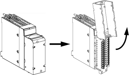
The following diagram shows the method for opening the terminal block cover so that it can be wired:
NOTE: The connection cable is installed and held in place by a cable clamp positioned below the 28-pin terminal block.
Labeling the Terminal Blocks
The labels for the terminal blocks are supplied with the module. They are to be inserted in the terminal block cover by the customer.
Each label has two sides: