Calibration Function of an Analog Module
(Original Document)
Introduction
This function is only accessible in online mode. It is used to recalibrate the channels of each analog input module of a project.
Calibration is used to correct the long-term module drift. It can also be used to optimize the precision of the measurement at ambient temperatures other than 25 degrees Celsius.
Procedure
Procedure for accessing the Calibration function:
Step
Action
1
Access the rack configuration screen.
2
Double-click the analog module to be calibrated.
3
Select the Calibration tab.
Result: the Calibration screen appears.
Illustration
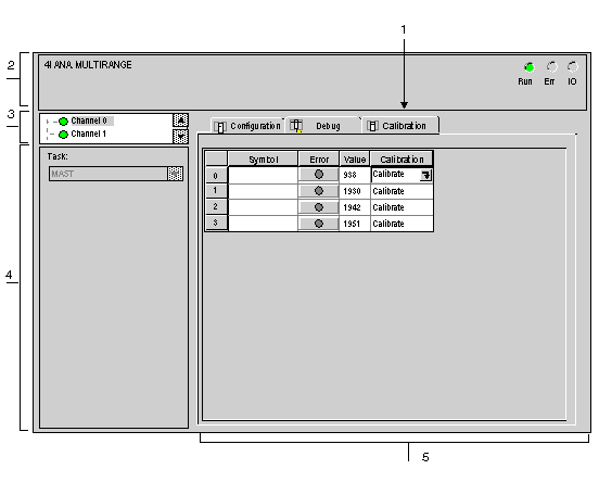
The figure below shows an example of a calibration screen.
Description
The table below shows the different elements of the calibration screen and their functions.
Number
Element
Function
1
Tabs
The tab in the foreground indicates the current mode (in this instance: Calibration). Every mode can be selected using the respective tab. The available modes are:
  • Calibration which can be accessed only in online mode,
  • Debug which can be accessed only in online mode,
  • Configuration.
2
Module area
Specifies the abbreviated heading of the module.
In the same area there are 3 LEDs which indicate the status of the module in online mode:
  • RUN indicates the operating status of the module,
  • ERR indicates an internal fault in the module,
  • I/O indicates a fault from outside the module or an application fault.
3
Channel area
Is used:
  • By clicking on the reference number, to display the tabs:
    • Description which gives the characteristics of the device.
    • I/O Objects which is used to presymbolize the input/output objects.
    • Fault which shows the device faults (in online mode).
  • To select a channel,
  • To display the Symbol, name of the channel defined by the user (using the variable editor).
4
General parameters area
Specifies the MAST, FAST or AUXi task configured. This heading is frozen.
5
Display area
This zone at "channel" level displays the ERR information for each channel: all the measurements are invalid; filtering and alignment are inhibited.
NOTE: All unavailable LEDs and commands appear in gray.
Use
For TSX AEY 800/810/1600, TBX AES 400 and TBX AMS 620 modules, only channel 0 needs to be calibrated for all the module channels to be calibrated.
For the TSX AEY 1614 module, only channels 0 and 8 need to be calibrated for all the module channels to be calibrated.
For the TSX AEY 414 module, general channel calibration must be performed.