Configuring an Analog Module: Overview
(Original Document)
At a Glance
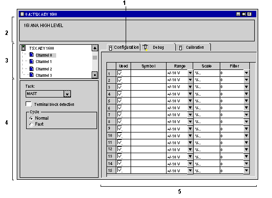
The Configuration screen for the analog module selected from the rack displays parameters associated with the module in question.
Illustration
This screen is used to display and modify parameters in offline mode.
Description
The following table shows the various elements of the configuration screen and their functions.
Number
Element
Function
1
Tabs
The tab in the foreground indicates the mode in progress (Configuration in this example). Select each mode by clicking on the corresponding tab.
  • Configuration,
  • Calibration which can be accessed only in online mode,
  • Debug, accessible only in online mode.
2
Module area
Displays the abbreviated module indicator.
In the same area there are 3 LEDs which indicate the status of the module in online mode:
  • RUN indicates the operating status of the module.
  • ERR signals a fault within the module.
  • I/O indicates a fault from outside the module or an application fault.
3
Channel area
Allows you:
  • By clicking on the reference number, to display the tabs:
    • Description which gives the characteristics of the device.
    • I/O Objects which is used to presymbolize the input/output objects.
    • Fault which shows the device faults (in online mode).
  • To select a channel,
  • To display the Symbol, name of the channel defined by the user (using the variable editor).
4
General parameters area
Use this area to select the task associated with the channel:
  • Task: defines the MAST, FAST or AUX0/3 task through which the channel's implicit exchange objects will be exchanged.
  • The Terminal block detection check box allows you to modify the terminal block detection function.
  • The Cycle field allows you to define the scan cycle for inputs (only available on some analog modules).
5
Configura-tion area
Use this area to set configuration parameters for the various channels. This area includes several topics, whose display varies depending on the analog module you've selected.
The Symbol column displays the symbol associated with the channel once it's been defined by the user (from the Variables Editor).