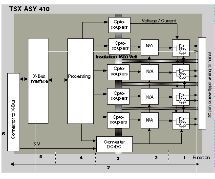
The TSX ASY 410 is a module with 4 analog outputs isolated from each other. This module offers the following ranges for each output, according to the selection made during
configuration :
-
+/-10 V,
-
0...20 mA,
-
4...20 mA.
The TSX ASY 410 output module performs the following functions :
Details of the functions are the following :
|
Address
|
Function
|
Characteristics
|
|
1
|
Connection to Process
|
-
hardware connection to the process through a 20-pin screw-type wiring terminal,
-
Protecting the module against voltage spikes.
|
|
2
|
Adaptation to Various Actuators
|
|
|
3
|
Converting Digital Data to Analog Signals
|
-
This conversion is performed on 11 bits with a polarity sign (-2048 to 2047),
-
Reframing the data provided by the program is performed automatically and dynamically by the converter,
|
|
4
|
Transforming application data into data directly usable by the discrete/analog converter
|
-
|
|
5
|
Interfacing and Communications with Application
|
-
Managing exchanges with the CPU,
-
Geographic addressing,
-
receiving, from the application, configuration parameters for the module and channels, as well as numeric setpoints from the channels,
-
sending module status back to application.
|
|
6
|
Module Power Supply
|
-
|
|
7
|
Module monitoring and sending error warnings back to application
|
-
Converter Test,
-
Testing for range overflow on channels,
-
verifying that terminal block is present,
|
The maximum delay between transmission of the output value on the PLC bus and its effective positioning on the terminal block is of 2.5 ms.
Outputs may be affected manually to the MAST task or to the FAST task from the application program.
The application must provide the outputs with values in the standardized format:
-
-10000 to +10000 for the +/-10 V range,
-
0 to +10000 in ranges 4-20 V and 0.-20 mA,
These values must be written in the words %QWr.m.c.0 to 3 for channels 0 to 3 of module.
