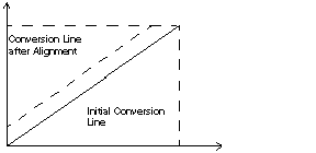
The process of "alignment" consists in eliminating a systematic offset observed with a given sensor, around a specific operating point. This operation compensates for an error linked to the process. Therefore, replacing a module does not require a new alignment. However, replacing the sensor or changing the sensor's operating point does require a new alignment.
Imagine we have a pressure sensor linked to a conditioner (1mV/mB), indicating 3200 mB, while we know the actual pressure to be 3210 mB.
The value measured by the module, in normalized scale, is 3200 (3,20 V). The user is able to align (or "map") his measurement to the desired value, namely 3200.
After the alignment procedure, the measurement channel will implement a systematic offset of +10. The alignment value you will need to capture is 3210.
The alignment value is
editable from the Control Expert screen, even if program is in RUN Mode.
For each input channel, you may:
-
View and modify the desired measurement value,
-
save the alignment value,
-
Determine whether the channel already has an alignment,
The alignment offset may also be modified through programming.
Channel alignment is performed in the Standard operating mode, without any effect on the module channels' operating modes. Maximum offset between measured value and desired (aligned) value may no exceed 1000.
The alignment offset is stored in the following word: %MWr.m.c.8.
