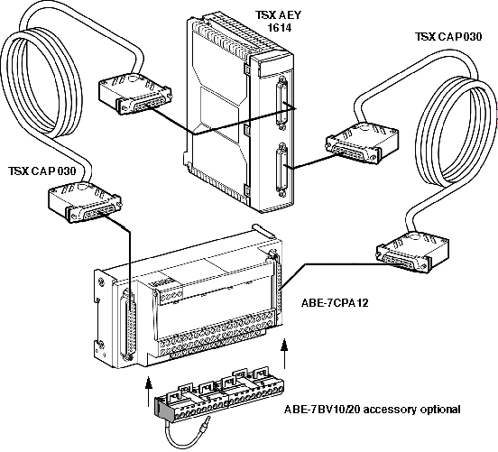
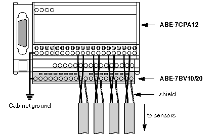
|
|
(Original Document)
|


|
TELEFAST 2 terminal block number
|
25 pin SubD connector pin number
|
Signal type
|
TELEFAST 2 terminal block number
|
25 pin SubD connector pin number
|
Signal type
|
|---|---|---|---|---|---|
|
1
|
/
|
Ground
|
11
|
/
|
Ground
|
|
2
|
/
|
Ground
|
12
|
/
|
Ground
|
|
3
|
/
|
Ground
|
13
|
/
|
Ground
|
|
4
|
/
|
Ground
|
14
|
/
|
Ground
|
|
100
|
2 (Sub D0)
|
IThc+ V0 / PT100_+supply
|
200
|
10 (Sub D0)
|
IThc+ V4
|
|
101
|
3 (Sub D0)
|
IThc- V0 / PT100_-supply
|
201
|
11 (Sub D0)
|
IThc- V4
|
|
102
|
4 (Sub D0)
|
IThc+ V1
|
202
|
14 (Sub D0)
|
IThc+ V5
|
|
103
|
5 (Sub D0)
|
IThc- V1
|
203
|
15 (Sub D0)
|
IThc- V5
|
|
104
|
6 (Sub D0)
|
IThc+ V2
|
204
|
16 (Sub D0)
|
IThc+ V6
|
|
105
|
7 (Sub D0)
|
IThc- V2
|
205
|
17 (Sub D0)
|
IThc- V6
|
|
106
|
8 (Sub D0)
|
IThc+ V3
|
206
|
18 (Sub D0)
|
IThc+ V7
|
|
107
|
9 (Sub D0)
|
IThc- V3
|
207
|
19 (Sub D0)
|
IThc- V7
|
|
108
|
2 (Sub D1)
|
IThc+ V8 / PT100_+measurement
|
208
|
10 (Sub D1)
|
IThc+ V12
|
|
109
|
3 (Sub D1)
|
IThc- V8 / PT100_-measurement
|
209
|
11 (Sub D1)
|
IThc- V12
|
|
110
|
4 (Sub D1)
|
IThc+ V9
|
210
|
14 (Sub D1)
|
IThc+ V13
|
|
111
|
5 (Sub D1)
|
IThc- V9
|
211
|
15 (Sub D1)
|
IThc- V13
|
|
112
|
6 (Sub D1)
|
IThc+ V10
|
212
|
16 (Sub D1)
|
IThc+ V14
|
|
113
|
7 (Sub D1)
|
IThc- V10
|
213
|
17 (Sub D1)
|
IThc- V14
|
|
114
|
8 (Sub D1)
|
IThc+ V11
|
214
|
18 (Sub D1)
|
IThc+ V15
|
|
115
|
9 (Sub D1)
|
IThc- V11
|
215
|
19 (Sub D1)
|
IThc- V15
|
|
Legend
|
|||||
|
+IThcx
|
+ input of the thermocouple for channel x
|
||||
|
-IThcx
|
- input of the thermocouple for channel x
|
||||