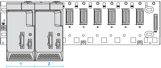
To create redundancy, install two redundant power supply modules in the first two slots of a BMEXBP••02 rack.
All other cases are considered as degraded mode.
|
Configuration
|
Monitor and save power supply data
|
Manage redundancy (power control and LED diagnostic)
|
Provide data to the application
|
|
Two redundant power supplies in a main rack including a M580 CPU or a CRA module
|
✓
|
✓
|
✓
|
|
Two redundant power supplies in an extension rack
|
✓
|
✓
|
–
|
|
One redundant power supply
|
✓
|
–
|
–
|
|
|
The redundancy principle is based on:
-
Each of the two redundant power supply modules in a rack is either the master or the slave.
-
An internal diagnostic (voltage and current) for each of the power supply modules.
-
An inter-communication between the two redundant power supply modules in a rack to increase the diagnostic level.
-
A redundancy status sends to the M580 CPU or CRA module.
Master and Slave Positions
Each of the two redundant power supply modules in a rack is either the master or the slave:
|
Mode
|
Description
|
|
Master
|
The master power supply module provides power to the backplane for both voltages (24Vdc and 3.3Vdc).
|
|
Slave
|
The other power supply module (not the master) is the slave.
|
After an initial power-up, the left-most power supply is the master:
1
Redundant power supply in the master position (after power-up).
2
Redundant power supply in the slave position (after power-up).
After the slave power supply assumes the role of master, it keeps the master configuration even if the other power supply is physically replaced. When a current master stops performing the role of master, the other power supply retrieves the master role. That is, the slave becomes the master when the original master stops providing power to the backplane. (Power is continuously supplied to the rack during this transition.)
Detecting Lost Redundancy
This Redundancy_Lost_N signal associated with the redundant power supply module is set to low when one of these conditions is true:
-
Master 24 Vdc is out of range.
-
Master 3.3 Vdc is out of range.
-
Slave 24 Vdc is out of range.
-
Slave 3.3 Vdc is out of range.
-
Master is not powered or absent.
-
Slave is not powered or absent.
-
Master current capability is insufficient.
-
Slave current capability is insufficient.
auto-test: An automatic test checks that the redundant power supply module is configured as the slave (S) power supply. During the test, the
ACTIVE and RD LEDs flash continuously.
NOTE: Each redundant power supply module monitors whether the 24 Vdc and 3.3 Vdc supplies are within the acceptable range before providing power to the backplane. If either supply is not in the acceptable range, the Redundancy_Lost_N signal is sent from the backplane to the CPU or the BMECRA312•0 module. The Redundancy_Lost_N signal describes the redundancy status of redundant power supply module when two such modules are connected on the backplane. This signal is active low and only used for CPU modules or BMECRA312•0 modules.
If the redundant power supply module is on a remote rack using an (e)x80 BM•CRA312•0 adapter module, the redundancy information is in the REDUNDANT_POWER_SUPPLY_STATUS field of T_M_CRA_EXT_IN. If the power supply is on a local rack, the redundancy information is reflected in %S124 and it is accounted for in %S10.
