Configuring a Local Slave
(Original Document)
Description
The Ethernet communication module presents three identical Local Slave configuration pages. Use each pages to configure a separate local slave instance. Create a local slave instance by:
To display this page, select one of the three Local Slave nodes in the navigation tree located on the left side of the Device Editor.
NOTE: Refer to the topic Configuring Properties in the Device Editor for instructions on how to edit properties.
The following steps describe a sample configuration for Local Slave 1. Your configuration may be different.
Configuration Example: Local Slave 1
In the sample network configuration, the application in the third-party PLC produces data, which is available in the PLC’s Ethernet communication module as inputs. In this example, the third-party device produces the following information:
Any information that needs to be passed to the third-party device—for example, confirmation that data from the third-party device has been received by the PLC—is accessible in the third-party device as input data. In this example, the third-party device is programmed to scan Local Slave 1 for this confirmation.
When configuring inputs and outputs in both the local slave and the third-party PLC, associate inputs and outputs as follows:
Associate these local slave items:
With these third-party PLC items:
Outputs (T to O)—assembly instance 101
Inputs—assembly instance 101
Inputs (O to T)—assembly instance 102
Outputs—assembly instance 102
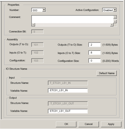
The configured Local Slave page looks like this:
Enabling and Naming the Local Slave
Use the Properties section of the Local Slave page to enable (or disable) and identify the local slave.
Setting
Description
Number
The unique number—or identifier—assigned to the device. By default, Control Expert assigns:
  • 000 = local slave 1
  • 001 = local slave 2
  • 002 = local slave 3
In this example, accept the default 000.
Active Configuration
  • Enabled activates the local slave.
  • Disabled de-activates the local slave, but retains the current local slave settings.
In this example, select Enabled.
Comment
An optional free text comment field up to 80 characters maximum.
In this example, leave blank.
Connection bit
Auto-generated integer (0 to 127) indicating the offset of the connection’s:
  • health bit, located in the input area
  • control bit, located in the output area
Note: This setting is auto-generated after the local slave settings are entered and the network configuration is saved.
Configuring the Size of Local Slave Input and Output Assemblies
Use the Assemblies section of the Local Slave page to configure the size of the local slave inputs and outputs. The assembly numbers are non-editable, and are assigned by Control Expert as follows:
Assembly number
Local slave number
Used for connection
101
1
T->O 1
102
1
O->T Exclusive Owner
103
1
Configuration
199
1
O->T Listen Only
111
2
T->O
112
2
O->T Exclusive Owner
113
2
Configuration
200
2
O->T Listen Only
121
3
T->O
122
3
O->T Exclusive Owner
123
3
Configuration
201
3
O->T Listen Only
1. In this table:
  • O indicates the originator—or scanner—device
  • T indicates the target—or adapter—device
The Local Slave assembly settings include:.
Setting
Description
Outputs (T->O)
A read-only value (see table, above).
In this example, 101.
Outputs (T->O) Size
The maximum size—in bytes—reserved for local slave outputs. An integer from 1 to 509.
In this example, only two output bytes are used: type in 2.
Inputs (O->T)
A read-only value (see table, above).
In this example, 102.
Inputs (O->T) Size
The maximum size—in bytes—reserved for local slave inputs. An integer from 0 to 509.
In this example, only eight input bytes are used: type in 8.
Configuration
A read-only value (see table, above).
In this example, 103.
Configuration Size
A read-only value set to 0.
NOTE: When using explicit messaging to read the Ethernet communication module’s assembly object, allocate sufficient room for the response, because the size of the response will equal the sum of:
   the assembly size + Reply service (1 byte) + General Status (1 byte)
Configuring Local Slave I/O Variable Names
Each input and output that Control Expert creates for your application has both a non-editable structure name (used by Control Expert to internally identify input and output items) and an editable variable name.
Use the I/O Structure Name section of the Local Slave page to:
The following property settings have been made in this example:
Setting
Description
Input:
Structure Name
The read-only name for input structures. By default, it is the concatenation of:
  • the prefix T_
  • the alias device name—in this case ETC01
  • the device number—in this case 01
  • the suffix _IN
In this case, the default would be T_ETC01_01_IN.
Variable Name
The editable base name for input variables. By default, it is the concatenation of:
  • the alias device name—in this case ETC01
  • the device number—in this case 01
  • the suffix _IN
In this case, the default would be ETC01_01_IN.
For this example, accept the default variable name.
Output:
Structure Name
The read-only name for output structures. By default, it is the concatenation of:
  • the prefix T_
  • the alias device name—in this case ETC01
  • the device number—in this case 01
  • the suffix _OUT
In this case, the default would be T_ETC01_01_OUT.
Variable Name
The editable base name for output variables. By default, it is the concatenation of:
  • the alias device name—in this case ETC01
  • the device number—in this case 01
  • the suffix _OUT
In this case, the default would be ETC01_01_OUT.
For this example, accept the default variable name.
If you have edited one or more variable names, you can restore the default variable names by clicking on the Default Name button.