|
Hardware Installation
|
|
|
Original instructions
|

|
Step
|
Action
|
Illustration
|
|---|---|---|
|
1
|
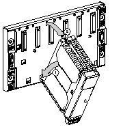
Place the prongs at the lower back of the module into the centering holes on the lower part of the rack.
|
 |
|
2
|
Swivel the module up and back to bring it into contact with the rack and the pin connectors.
|
|
|
3
|
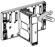
Secure the module to the rack by tightening the screw on the upper part of the module.
Note: Maximum tightening torque is 2.0. N.m.
|
 |
 WARNING WARNING |
|
HAZARD OF ELECTRICAL SHOCK OR BURN
Connect the ground wire to the protective earth (PE) terminal before you establish any further connections. When you remove connections, disconnect the ground wire last. The Ethernet cable shield must be connected to PE ground at the Ethernet switch.
Failure to follow these instructions can result in death, serious injury, or equipment damage.
|
