Multi-Module Communication
Original instructions
At a Glance
This topic explains communication capabilities across modules and devices in a PLC configuration. Different modules and devices are available providing access to USB, Modbus and/or Ethernet communication:
Overview
A maximum of two NOE modules can be installed on a PLC configuration.
Therefore, the maximum number of configured Ethernet links is three:
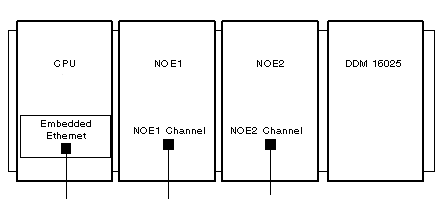
The following illustration shows a possible configuration:
This example describes a rack with four modules:
NOTE: To define the rack/slot combination [x.x]:
  • first digit = rack number
  • second digit = slot number
Communication Overview and Definitions
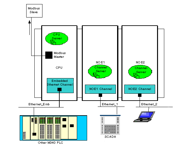
The following illustration presents the overall installation:
In this example, there are:
The following table defines the terms that are used to describe communication methods using multiple communication modules:
Term
Definition
Channel
Represents the communication channel itself, able to manage the dispatching of the messaging flow.
Channel Server
A server dedicated to the management of the communication channel itself. For example, it provides statistical information on an Ethernet link. Control Expert accesses this server to display information related to an NOE module, for example.
CPU Server
This server answers all requests sent to the CPU, whatever the communication media used to access it.
Routing Table
The following table describes the communication capabilities across the different modules:
Destination →
NOE1 Channel Server
NOE1 Channel
NOE2 Channel Server
NOE2 Channel
CPU Ethernet Channel
CPU Modbus Master
Source ↓
NOE1 Channel
supported
not supported
supported
not supported
not supported
supported
NOE2 Channel
supported
not supported
supported
not supported
not supported
supported
CPU Ethernet
supported
not supported
supported
not supported
not supported
supported
CPU USB
supported
supported
supported
supported
supported
supported
CPU Modbus Slave
supported
supported
supported
supported
supported
not supported
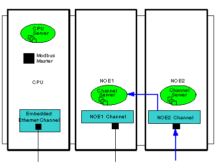
Example 1: NOE2 Channel to NOE1 Channel Server
The following illustration describes the connection from an NOE2 channel (source) to an NOE1 channel server (destination). The same methodology can be implemented from an NOE1 channel to an NOE2 channel server:
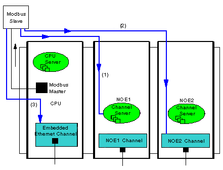
Example 2: CPU Modbus Slave to NOE Channel, NOE Server Channel, CPU Ethernet Channel
This example describes the connection from a CPU Modbus slave to:
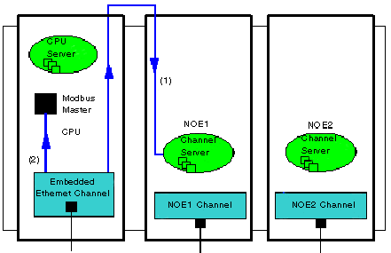
Example 3: CPU Ethernet to NOE Channel Server, CPU Modbus Master
This example describes the connection from a CPU Ethernet to:
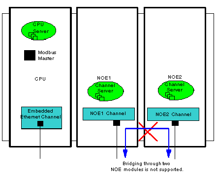
Example 4: Not Supported - NOE1 Channel to NOE2 Channel Not Supported
This example illustrates a configuration that is not supported, with communication from an NOE1 channel to an NOE2 channel: