|
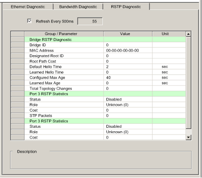
Communication Module RSTP Diagnostics
|
|
|
Original instructions
|
|
When the checkbox is...
|
This page...
|
|---|---|
|
Selected
|
|
|
De-selected
|
|

|
Step
|
Action
|
|---|---|
|
1
|
In the DTM Browser, select the communication module and click the right mouse button. A pop-up menu opens.
|
|
2
|
In the menu, select Device menu → Diagnostic.
|
|
3
|
In the left pane of the Diagnostic window, select the communication module node.
|
|
4
|
Click on the RSTP Diagnostic tab to open that page.
|
|
Parameter
|
Description
|
|---|---|
|
Bridge RSTP Diagnostic:
|
|
|
Bridge ID
|
An 8-byte bridge identification field is comprised of a 2 sub-fields:
|
|
MAC Address
|
The Media Access Control address of a device, found on the front of the module.
|
|
Designated Root ID
|
The Bridge ID of the root switch.
|
|
Root Path Cost
|
The aggregate cost of port costs from this switch back to the root switch.
|
|
Default Hello Time
|
The interval at which Configuration BPDU messages will be transmitted during a network convergence. For RSTP this is a fixed value of 2 seconds.
|
|
Learned Hello Time
|
The current Hello Time value learned from the root switch.
|
|
Configured Max Age
|
The value that other switches use for MaxAge when this switch is acting as the root. Valid range: 6 to 40
|
|
Learned Max Age
|
The maximum age learned from the root switch. This is the actual value currently used by this switch.
|
|
Total Topology Changes
|
The total number of topology changes detected by this switch since the management entity was last reset or initialized.
|
|
Ports 3 and 4 RSTP Statistics:
|
|
|
Status
|
The port's current state as defined by RSTP Protocol. This state controls the action the port takes when it receives a frame. Possible values are: disabled, discarding, learning, forwarding.
|
|
Role:
|
The port’s current role per RSTP protocol. Possible values are: root port, designated port, alternate port, backup port, disabled port.
|
|
Cost
|
The logical cost of this port as a path to the root switch. If this port is configured for AUTO then the cost is determined based on the connection speed of the port.
|
|
STP Packets
|
A value in this field indicates that a device on the network has the STP protocol enabled.
NOTE:
|