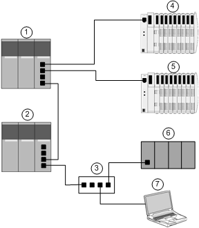
This manual describes the creation of a complete Ethernet network configuration for the following topology:
1
Primary PLC incorporating the BMX NOC 0401 Ethernet communication module
2
A secondary PLC that “listens” to the scan of the primary PLC local slave by the third-party scanner
3
Ethernet managed switch
4
Advantys STB island, with an STB NIC 2212 EtherNet/IP network interface module plus 8 I/O modules
5
Advantys STB island, with an STB NIP 2212 Modbus TCP network interface module plus 8 I/O modules
6
Third-party PLC that scans a local slave in the primary PLC (1)
7
PC equipped with both Control Expert configuration software (upgraded with the Ethernet Configuration Tool that ships with the BMX NOC 0401 Ethernet communication module) and Advantys configuration software, used to configure communication settings for Ethernet communication module in the primary PLC (1) and the remote network interface modules on the STB I/O islands (4 and 5)
Multiple Roles of the PLC and Ethernet Communication Module
The PLC, and in particular the BMX NOC 0401 Ethernet communication module, can be configured to simultaneously perform multiple roles with respect to other network devices. In this sample network, you will learn how to configure the communication module to operate as:
-
a scanner of devices that use the EtherNet/IP (4) and the Modbus TCP (5) protocols
-
an adapter—also known as a local slave—that produces output data that both the remote third-party PLC (6) and secondary PLC (2) can read as input data
-
a DHCP server that provides IP address settings to other devices on the Ethernet network
-
an FDR server that provides operational settings to devices on the Ethernet network that also receive their IP address from the DHCP server, above
