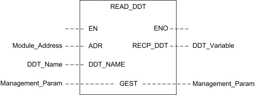
Overview
Use the READ_DDT function block
to configure read messages for the BMENUA0100 communication module.
The ADR, the DDT_NAME, and the GEST parameters
define the operation.
EN and ENO can be configured as additional parameters.
FBD Representation

Input Parameters
Parameter |
Data type |
Description |
|
|---|---|---|---|
|
BOOL |
This parameter is optional. When this input is set to one, the block is activated and can solve the function blocks algorithm. When this input is set to zero, the block is deactivated and won’t solve the function block algorithm. |
|
|
Any Array of |
Array containing the address of the destination entity of the exchange operation. The address is the result of the ADDMX function. (For example: ADDMX(0.0.3{192.168.10.2}100.TCP.MBS) indicates the module at IP address 192.168.10.2, with UnitId 100 (local server of the module), connected to the embedded Ethernet port. |
|
|
STRING |
Name of DDT to read: T_BMENUA0100 |
|
Input/Output Parameters
The GEST array is local:
Parameter |
Data type |
Description |
||
|---|---|---|---|---|
|
Array [0...3] of |
The management parameters, consisting of four words. Refer to the Control Expert help topic Structure of the Management Parameters for additional information regarding these parameters. |
||
Word# |
Most Significant BYTE |
Least Significant BYTE |
||
0 |
Exchange number |
Activity bit: rank 0 Cancel bit: rank 1 Immediate knowledge bit: rank 2 |
||
1 |
||||
2 |
||||
3 |
||||
Output Parameters
Parameter |
Data type |
Description |
|---|---|---|
|
BOOL |
This parameter is optional. When you select this output you also get the EN input. ENO output is activated upon successful execution of the function block. |
|
Any |
Reception buffer. A DDT variable may be used. Refer to the T_BMENUA0100 DDT description for the content of this DDT. The size of the data received (in bytes) is written automatically by the system in the fourth word of the management table. |
Asynchronous Communication Function Block
In a Hot Standby application during a switchover event, the READ_DDT asynchronous communication function block does not automatically resume operation on the new Primary PAC, unless specifically configured, as follows.
Use the following procedure to allow asynchronous communication EFBs to automatically resume operation after a switchover:
Program your application so that all EFB instances are not exchanged with the Standby PAC. To do this, de-select the attribute for the EFB instance.
Considerations when Configuring the Function
When using the READ_DDT EF, consider the following:
If your application includes more than one BMENUA0100 in a rack, use separate instances of a WORD array for each GEST pin. Each block manages it own management WORD array.
You do not need to specify a value for the length parameter in GEST[3], because there is no data to send. At the end of the operation (when the activity bit in GEST[0] is set to 0), the length will be set with the length of the data copied into the RECP_DDT output parameter if no detected error is reported in GEST[1] or with an additional status code. Refer to the Control Expert help topic Error Codes of EFBs with STATUS parameter for a description of these additional status code values.
A timeout value of 0 indicates an infinite waiting period. In this case, a communication delay or loss occurring during the exchange operation is not detected. During this infinite waiting period, the RECP_DDT parameter retains its previous value. To avoid this scenario, set the timeout to a non-zero value.
In case of operation report 16#01 (Request not processed) or 16#02 (Incorrect response) in the GEST[1] word of the management table, an additional status code may be reported in the length parameter (GEST[3]). Status codes returned in this field correspond to a subrange of the possible STATUS parameter codes of communication EFBs. Possible values for the READ_DDT are 0x30ss and 0x4001. Refer to the Control Expert help topic Error Codes of EFBs with STATUS parameter for a description of these additional status code values.
Depending on the DDT specified in the DDT_NAME parameter, some consistency checks will be performed on the data received. If a mismatch is detected, code 16#02 (Incorrect response) is set in the operation report byte (the most significant byte of GEST[1]). Note that the block does not check the data type validity of the variable configured as the reception buffer (RECP_DDT). Verify that the data type of the variable linked to the RECP_DDT parameter matches the type of data received.
| CAUTION | |
|---|---|
Configuring the READ_DDT Elementary Function
To configure the READ_DDT elementary function, follow these steps:
Step |
Action |
|---|---|
1 |
Set the address of the destination device in ADR (use an ADDM block to specify this address in an explicit string format). |
2 |
Set DDT_NAME parameter with the name of the DDT to read. |
3 |
Call the READ_DDT function to launch the communication (with EN input pin set to 1 if configured). |
4 |
Monitor the activity bit (in the least significant byte of the GEST[0] parameter) until the communication is completed (the activity bit is set to 0 by the system when the communication has ended). Execute this function only once to avoid erasing the status values. For example, setting the EN pin to 0 during operation would cause the function to be called again. |
5 |
View the report parameters in GEST[1]. If the report reads 16#0000, then RECP_DDT buffer has been filled with received data. Size of the data received (in bytes) is written in the fourth word (GEST[3]) of the management table. |
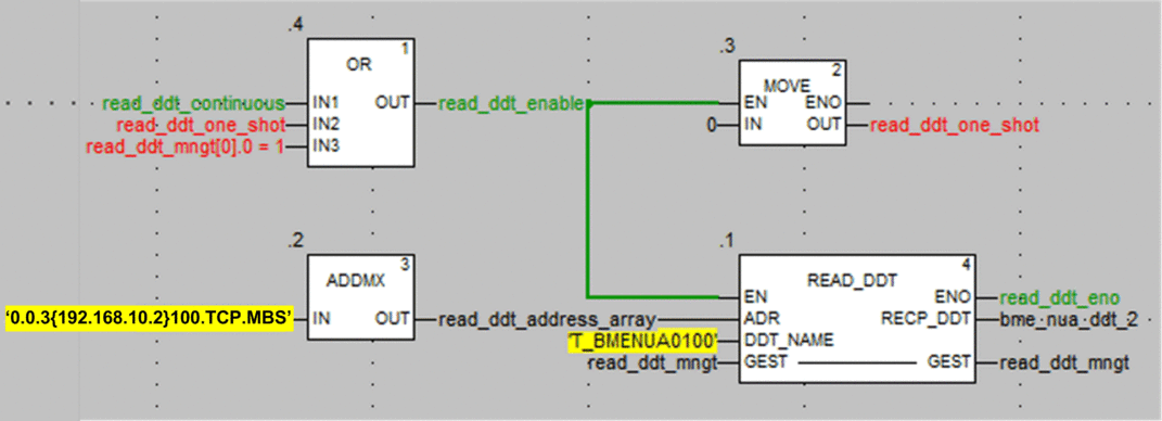
READ_DDT EF Example

In this example, the READ_DDT EF may be started:
Continuously by setting the read_ddt_continuous variable.
NOTE: In the event of a detected error, report codes in the second word of the read_ddt_mngt variable cannot be read.Only one time, by setting the read_ddt_one_shot variable.


