Architecture

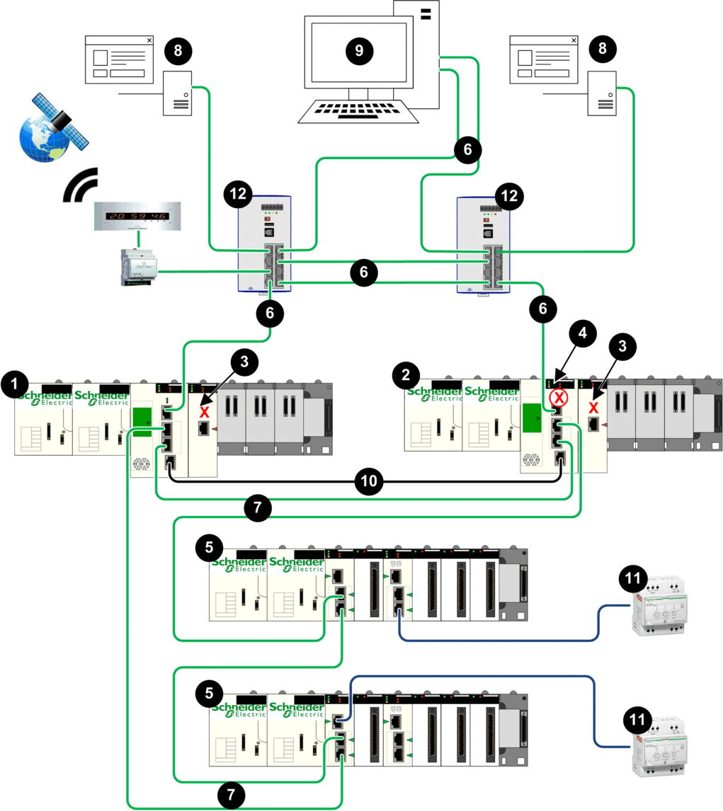
1 Primary Hot Standby PAC
2 Standby Hot Standby PAC
3 BMENUA0100 with control port disabled
4 Standby CPU with automatic blocking of service port
5 X80 Ethernet RIO drop
6 Control network
7 Ethernet RIO main ring
8 OPC UA client (SCADA system)
9 Engineering workstation with dual Ethernet connections
10 Hot Standby communication link
11 Distributed equipment
12 Dual ring switch (DRS)
Description
This architecture provides redundant connections from M580 Hot Standby CPUs to dual OPC UA clients (SCADA systems). Its primary purpose is to provide high availability to the Hot Standby PACs. For that reason, this architecture presents a non-isolated flat network, joining together the control network and the Ethernet RIO main ring in a single subnet.
The BMENUA0100 control port is disabled. IPv4 Ethernet communication to the BMENUA0100 module is provided over the backplane port. Upstream communication from the Hot Standby PACs to the SCADA servers is accomplished via the primary CPU service port. The CPU device ports provide downstream connectivity to the Ethernet devices on the Ethernet RIO main ring.
The standby CPU service port (4) is automatically disabled, which is accomplished by using the Control Expert configuration software to select in the tab of the configuration for both the primary and standby CPUs.
In this flat network design, all devices, including the CPU, CRAs, and the BMENUA0100 can be clients of the same NTP server that resides in the control network. Hence, CPU time is synchronized with the BMENUA0100 module.
The BMENUA0100 supports applicative time stamping. In this process, time stamping modules record events in their local buffer. These time stamped events are consumed by the application running in the PAC, which converts the raw record data and stores it in a usable format. The formatted records can then be consumed by a supervisory application, such as a SCADA system.


