Generating Events in the Server
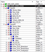
In the server DTM configuration tab, the device DDT structure (unlocated variable) looks like this:

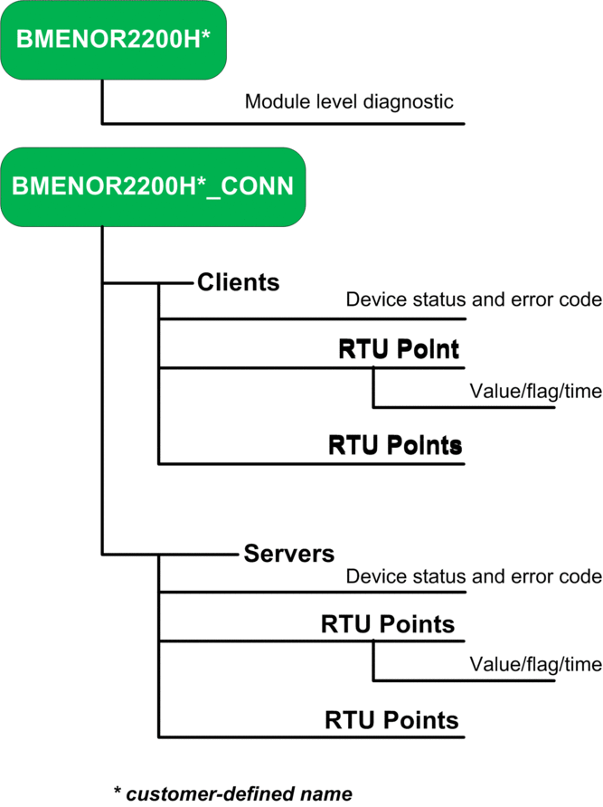
Graphical Representation

Correspondences
These correspondences apply to the above DDT structure and graphical representation:
The customer-defined variable name corresponds to the T_BME_NOR type.
The client corresponds to these RTU points:
Device_State: BYTE type
Error_Code: WORD type
AI_Px: Analog_input_xxx Type
NOTE: When the point count is less than 1, the point type uses theARRAYformat.BOSt_P0_P0: Bin_Output_xxx type
BI_P0_P0: Binary_Input_xxx type
TmSync_0000_CB: Time_Sync type
BCnt_P0_P0: Counter_... type
The server corresponds to these RTU points:
Device_State: BYTE type
Error_Code: WORD type
BI_P0_P0: Binary_Input_xxx type
DI_P0_P0: Double_Input_xxx type
AI_P0_P0: Analog_Input type (Flags, Timestamp, Value)
AO_P0_P0: Analog_Output type
BI_P10_P10: Binary_Input_xxx type
Event_STAT_BinaryInput: WORD type (counter); BYTE type (overflow)
Event_STAT_BinaryOutput: WORD type (counter); BYTE type (overflow)
Event_STAT_AnalogInput: WORD type (counter); BYTE type (overflow)


