

Introduction
The event routing component allows events from sub stations to be routed to SCADA within a single BMENOR2200H module.
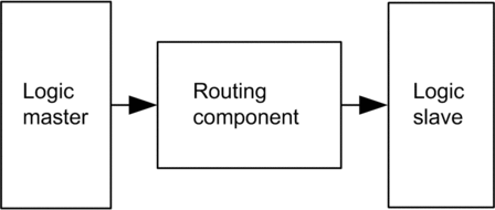
To route events, one or more RTU client channels and at least one RTU server channel are needed inside the system. The solution is to create a logic RTU client and server in a single BMENOR2200H module. In the logic client, points are created to represent points in sub stations, and in the logic server, points are created to simulate the behavior of points in sub stations. The event routing component is responsible for collecting events in the logic client. These events are sent from sub stations and trigger the same events in the logic server.
BMENOR2200H module components:
There are no automatic event routing capabilities between two BMENOR2200H modules (a server and a client) that are configured in the same station.
In a hierarchical architecture, time stamped events are automatically transferred from low-end server sub stations to the SCADA (or client) through the station. The automatic transfer uses path-through events functionality with a single BMENOR2200H module configured in both the client and server.
Configuration
Configure the BMENOR2200H module for event routing on the data mapping configuration page.
Considerations:
The BMENOR2200H module does not detect events for event routing points in a server.
There is no web page to configure event routing.
In a valid configuration for event routing points, only one point is occupied in the database to reduce the data size stored in memory. Use the device DDT to see the point and its structure in the Variables list.
Point configuration considerations:
Configuration |
Description |
|---|---|
channel (See the note below.) |
For routing events, configure one client channel and at least one server channel. One client channel is required so that the system can connect with more sub servers, and more server channels allow for more SCADA in the system. NOTE: Refer to the channel configuration instructions.
|
client data mapping (See the note below.) |
Add data points in the client channel. These points show the mapping of client points in the sub server, which communicate with the client channel. NOTE: Refer
to the DNP3 data object
mapping instructions.
|
server point |
After you configure the points in the client channel, the corresponding point is listed in the server channel. The points used to route are different from the normal points of the server. The parameters (CPU type, CPU address, variable name, and time stamp) of CPU mapping are no longer available, and the available parameters are read only. Their lifetime is consistent with peer point configuration in the client. |
NOTE: When
you configure these points in the client channel, select the events
of the points to be routed, and route events to the corresponding
server channel.
For example, if the client channel receives events from the sub server Binary Input point and routes them to the logic server channel, they become events of the Binary Input point of logic server channel. Considerations:
|
|
Channel Combination for Event Routing
To route events inside the BMENOR2200H module, use the configuration instructions to combine the client channel and server channel.
The supported combinations are:
Client Channel |
Server Channel |
|---|---|
DNP3 net client |
DNP3 net server |
DNP3 serial client |
DNP3 net server |
IEC60870-5-101 client |
IEC60870-5-104 server |
IEC60870-5-104 client |
IEC60870-5-104 server |
Limitations
Events are routed inside the module. This means that it is not possible to route events between two or more modules and also that the PLC application in the CPU cannot get and process the events. (The CPU can still get the point value in events just like the standalone client channel.)
Only events are routed. Requests (commands) from SCADA are not routed to the sub server. This means that inside the BMENOR2200H module, there is no other data exchange or communication between the client channel and the server channel except for events. Not all client and server channel combinations are supported by the event routing function.
In the system, SCADA cannot communicate with sub servers. The solution uses the logic server in the BMENOR2200H module to simulate sub servers, so SCADA can communicate only with the logic the server in the BMENOR2200H module, and the sub server can communicate only with the logic client in the BMENOR2200H module.
Some information related to events may be changed. Key information related to events like point value, flag, and time stamp is kept during event routing. Other information related to events like point number, events class, and variation is changed according to the client channel configuration.
For broken connections, the downstream server does not generate events to an upstream supervision system.
Events Buffer Size
Confirm that the events buffer of the server are greater than the events buffer in the sub server.