Use these instructions to install an communications module in a single slot on the Ethernet backplane.
NOTE: Fitting operations (installation, assembly, and disassembly) are described below.
Before Installing a Module
Before installing the Ethernet communications module, remove the protective cap from the module connector on the rack.
Install the Ethernet communications module in a single slot on a BMEXBP•••• Ethernet backplane.
Installing the Module on the Rack
Mount the module in a single slot on the backplane:
|
Step
|
Action
|
|
1
|
Turn off the power supply to the rack.
|
|
2
|
Remove the protective cover from the module interface on the rack.
|
|
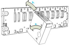
3
|
a: Insert the locating pins on the bottom of the module into the corresponding slots in the rack.
b: Use the locating pins as a hinge and pivot the module until it is flush with the rack. (The twin connector on the back of the module inserts into the connectors on the rack.)
|
|
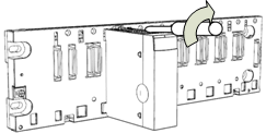
4
|
Tighten the retaining screw to hold the module in place on the rack:
Tightening torque: 0.4...1.5 N•m (0.30...1.10 lbf-ft).
|
Do not apply power to the Ethernet communications module until connections are made at both ends of the Ethernet cable. For example, connect the cable to both the module and another device (adapter module) or a before you turn on the power.
Refer to your system hardware reference manual for details about the s.
Use fiber-optic cable to establish a communications link when it is not possible to equalize the potential between the two grounds.
NOTE: Refer to the ground protection information provided in the
Electrical installation guide and
Control Panel Technical Guide, How to protect a machine from malfunctions due to electromagnetic disturbance.
Any Ethernet communications module on the rack can be replaced at any time with another module with compatible firmware. The replacement module obtains its operating parameters over the backplane connection from the CPU. The transfer occurs immediately at the next cycle to the device.


 DANGER